
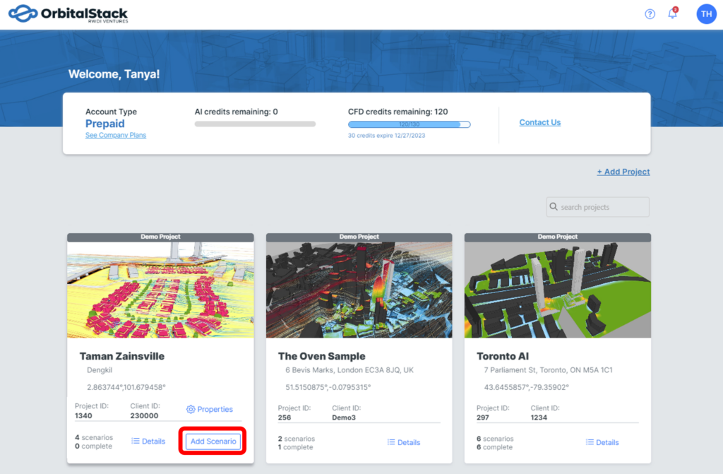
On the Projects Dashboard, find your project tile and click “Add Scenario“.
Orbital Stack supports both AI and Rapid CFD within Microclimate simulations. For Cladding simulations, we exclusively utilize our AI engine.
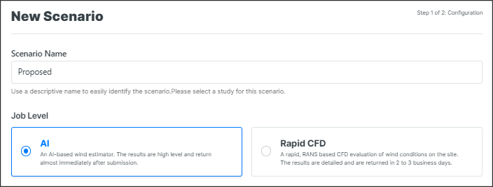
Please select the type of scenario you want to create:
1. Microclimate
1.1 Add a New Scenario
In the pop-up window, choose a name for your scenario and select the Job Level (type of simulation) you would like to run:
- AI Engine
- Rapid CFD
*IMPORTANT: Explore the differences between AI and CFD by reading Choosing Your Simulation Approach – AI vs CFD.
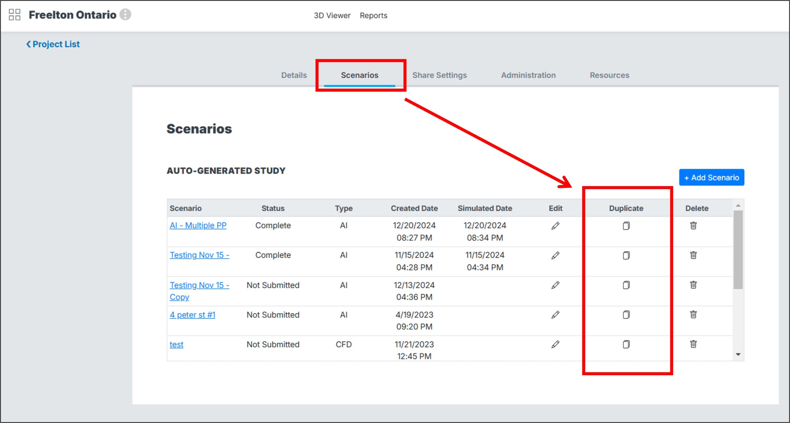
• Duplicate Scenario
To duplicate the geometry, metrics, and/or parameters of a previously run scenario, go to the Project Properties section, navigate to the Scenarios tab, and click Duplicate next to the scenario you wish to copy.
• Select Output Metrics
Under the analysis section, choose Pedestrian Level Wind and select your metrics.
Thermal Comfort analysis is offered as a complementary option and must be specifically chosen as such.
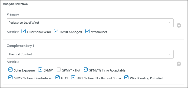
RWDI Abridged: A modified version of RWDI’s Pedestrian Wind Comfort Criteria, simplified to acknowledge the more approximate results generated by AI simulations, or limited wind-direction CFD simulations.
Directional Wind: Directional arrows, or glyphs, are used to visualize the directional flow by positioning 3-dimensional vector arrows at locations across the presentation plane.
Streamlines: Generalized wind flows are shown in color-coded streamlines. This feature is available in all CFD simulations, but exclusively available to monthly subscribers for AI simulations.
Solar Exposure: Identifies where shadows would generally fall for the given season and time or day.
SPMV*: Standard Predicted Mean Vote Modified accounts for the physics associated with elevated solar exposure and humidity ranges present.
- SPMV % Time Acceptable
- SPMV % Time Comfortable
- SPMV* – Hot: Hot and Tropical Climates
UTCI: Universal Thermal Comfort Index quantifies how people perceive given weather conditions by equating them to an equivalent temperature based on standard conditions.
- UTCI % Time No Thermal Stress
Wind Cooling Potential: Provides the average wind speed of a location at an indicated time.
IMPORTANT: To learn more about the metrics available, please visit our knowledge base page.
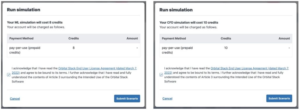
The next step is a summary of the scenario configuration, and identifies the amount of credits (AI/CFD) this scenario will cost you:
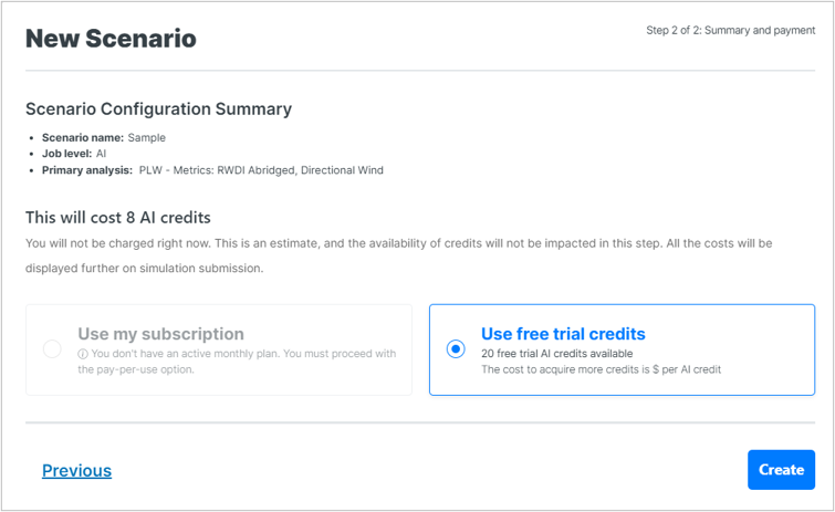
AI simulations:
- Pedestrian Level Wind – 8 AI credits
- Thermal Comfort cost an additional 4 AI credits for 2 seasons or 8 AI credits for 4 seasons. Thermal Comfort must be added as a complementary analysis onto a Pedestrian Level Wind simulation.
CFD simulations:
- Pedestrian Level Wind – 7 CFD credits
- Thermal Comfort cost an additional 3 CFD credits for 2 seasons or 7 CFD credits for 4 seasons
You may choose to purchase the simulation using credits from an active subscription plan or on a Pay-per-Use basis*.
*Note: Pay-Per-Use must to be enabled for your account and for your company. If this option is not available, please contact your company administrator and/or set up an agreement through sales@orbitalstack.com.
When you are finished, click “Create” to begin setting up your simulation.
1.2 Upload and Categorize Geometry
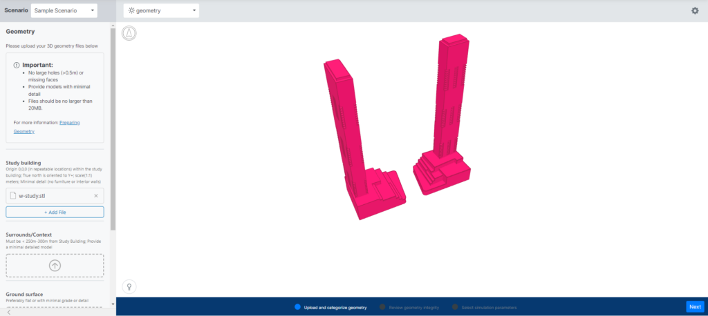
To begin setting up your simulation, upload your geometry files into the corresponding buckets appearing to the left of the screen.
Files must be exported from your CAD software and uploaded in STL file format.
IMPORTANT: Before uploading your Geometry, ensure it has been correctly prepared. Quick tips and detailed instructions can be found on our Preparing Geometry post.
Upload all the required Geometry files by dragging and dropping the files or by clicking the buckets and locating the files directly on your computer. STL Files include:
- Study Building: The main structure of the analysis
- Surrounds/Context: Surrounding structures within 300m of the Study location
- Ground Surface: The terrain around the study building and surrounding area
- Presentation Plane(s): The areas where you would like to see results visualized (ex. street level, rooftops, podia etc). Ensure that you have raised these 1.5 meters above the surface for which you want results visible. All presentation planes are to be exported separately or according to the desired presentation groupings, i.e. ground level, above grade, balconies, etc.
- Overlay: The streets and sidewalks layer for visualization only. Does not influence simulation results, and should be raised 1.7m above grade to be visible over results.
The following are exclusively available for CFD simulations only:
- Landscaping: any large trees or large clusters of shrubs. Please indicate porosity in Scenario Notes Section
- Mitigations: any features that would be installed for mitigation measures (ex. screens, canopies etc.)
As you upload your Geometry files, they will appear in the preview window to the right of the screen.
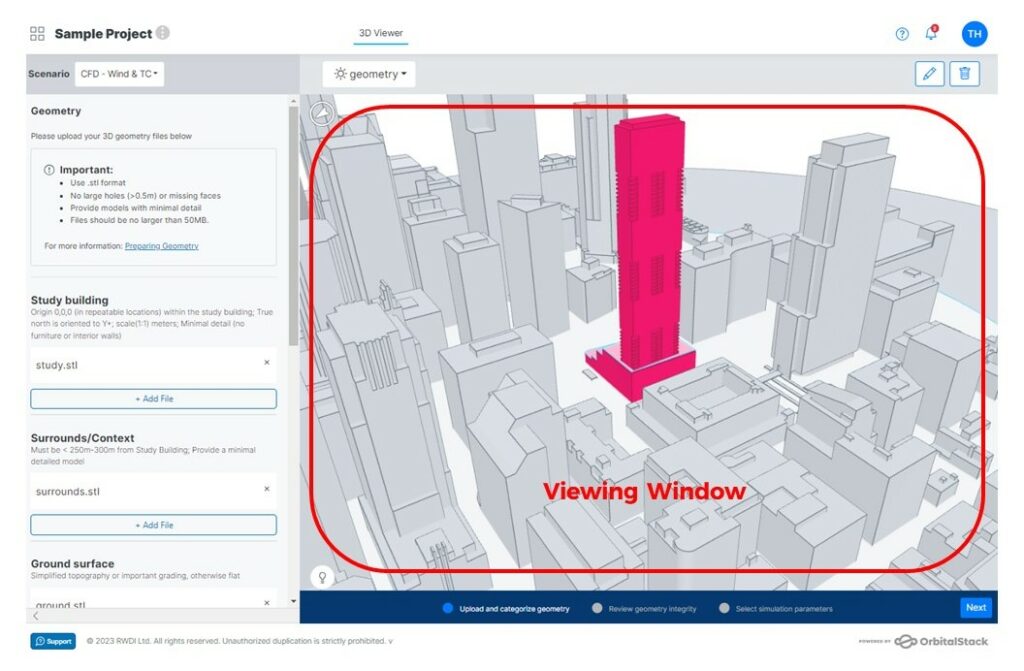
Within the preview window, click the lightbulb icon at the bottom-left for tips on how to spin and rotate your model to make sure everything aligns as expected.
Once all of your geometry files are uploaded, proceed to the next step by navigating to the bottom right of the page and clicking “Next“.
• Review Geometry Integrity
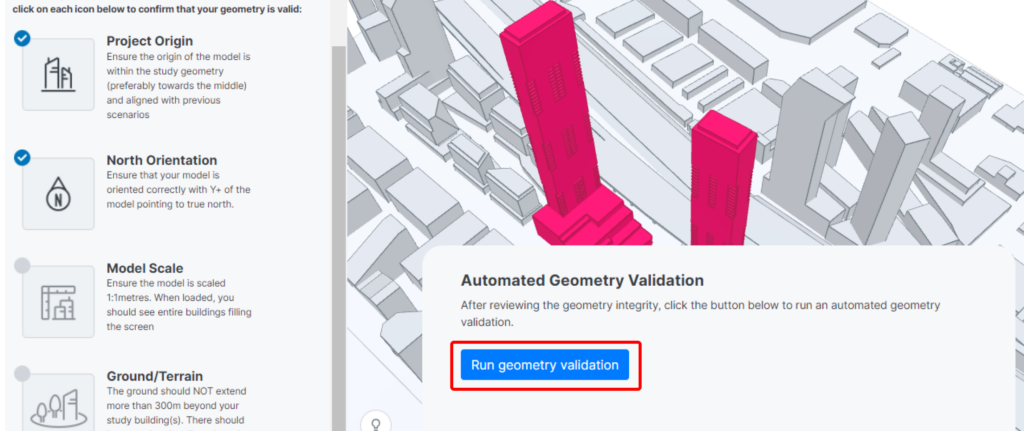
Before finalizing your simulation parameters, we strongly recommend checking your files to confirm that they are formatted properly in accordance with the considerations which appear on the left of the screen. The viewer will ask you to check off each of these items before moving on to select simulation parameters, though this is not strictly necessary.
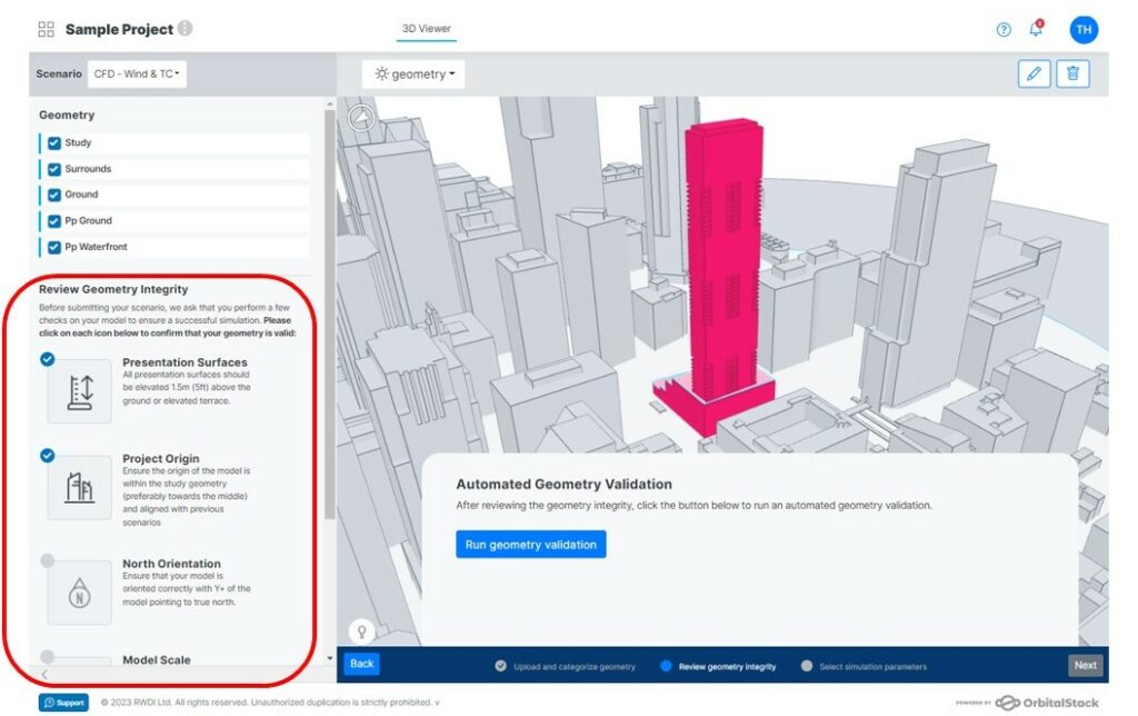
You are now prompted to “Run Geometry Validation”
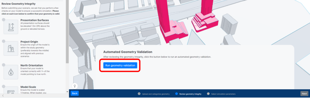
The viewer will warn you of potential issues within your geometry, i.e. surfaces are volumetric when they should be a single flat surface or presentation planes are are not raised high enough. If this happens, you can click the button “Fix Geometry Files” which will take you back to the geometry upload page allowing you to remove your file and reupload a corrected file.
If no issues were found in your geometry files, you can proceed by clicking “Next” in the bottom right of the screen.
IMPORTANT: You can move forward without rectifying your geometry during the validation process. However, it’s crucial to understand that depending on the issue, it may impact your results.
1.3 Select Simulation Parameters
For a Pedestrian Wind Analysis, you will be asked to select the RWDI Abridged and Wind Direction parameters.
If you have requested Thermal Comfort, you will also be asked to select the specific parameters for the metrics you have chosen, i.e. SPMV*, Solar, Wind Cooling Potential, and UTCI.
• RWDI Abridged Parameters
You are now required to set the parameters for your seasons under the RWDI Abridged tab. You may use the default settings, customize them to your preference or copy them from one of the other parameters that have already been selected.
IMPORTANT: Seasons must cover a range of at least 2 months. Time ranges must cover a range of at least 3 hours. Otherwise, an error message will appear near the bottom of the pop-up window.
• Wind Directions & Terrain
You can now navigate to the tab labeled “Wind Directions” to customize your wind parameters.
If you are only simulating a few wind directions, we recommend that you pick the ones that are most common at that site up to a maximum of 8. At any location, conditions are always dominated by the prevailing winds.
To ensure that you have some statistical confidence in the combined Pedestrian Wind Comfort results, it is recommended that there be a minimum of six directions (eight preferred) and that those directions correspond to the most common winds.
If you are unsure of which directions to choose, we recommend that you go with the default eight directions, spread evenly around the compass.
For each wind direction, you are required to select an upwind terrain (aka roughness). If you are unsure of which terrain type to choose, we recommend using a tool such as Google Maps to identify the terrain type adjacent to the site for each direction. For further guidance, check out: Wind Directions and Terrain Considerations (AI)
• SPMV* Parameters
This option will only appear if you have requested the complementary Thermal Comfort analysis at the scenario creation stage.
The SPMV* Parameters include Seasons, Time of Day, Clothing Profile and Activity.
- Seasons – can be customized, copied from other parameters, or you can choose the default options.
- Time of Day – can be customized or you can choose the default option. For additional guidance, please check out Time Slicing Profiles
- Clothing Profile – choose the clothing type that aligns best with the intended activity of your site. For additional information, check out: Clothing Profiles
- Activity – choose the activity that closest matches the intended use of your space. For additional information, check out: Activity Types
• Solar, Wind Cooling Potential, and UTCI Parameters
These options will only appear if you have requested the complementary Thermal Comfort analysis and their corresponding metrics at the scenario creation stage.
These Parameters include Seasons and Time of Day. All can be customized, copied from other parameters, or you can choose the default options.
1.4 Submission

Once you are satisfied, click “Submit“.
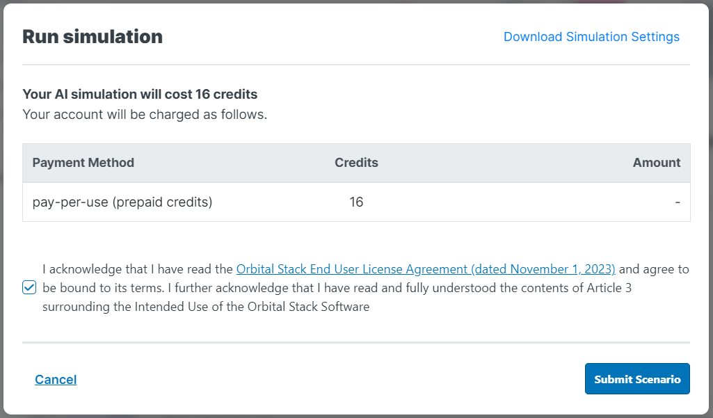
A pop-up window will appear confirming the total cost of the simulation (in credits). Once you have checked the box to confirm that you have read the Terms and Agreement, click “Submit Scenario“.
After submitting an AI simulation, the page will refresh and results will render within a few minutes*.
After submitting a CFD simulation, you will receive an email confirmation. All results should be available within 2-3 business days*. If we run into any issues, we will contact you directly.
*Note: If there are issues with your submission (i.e. unprepared geometry and/or unaligned Simulation Parameters), results may take additional time.
Please do not hesitate to Contact Us with any questions!
2. Cladding
2.1 Add a New Scenario
In the pop-up window, choose a name for your scenario and select AI at the Job Level (type of simulation) you would like to run. Cladding simulations are run exclusively through our AI engine.
Under the analysis section, select Cladding AI
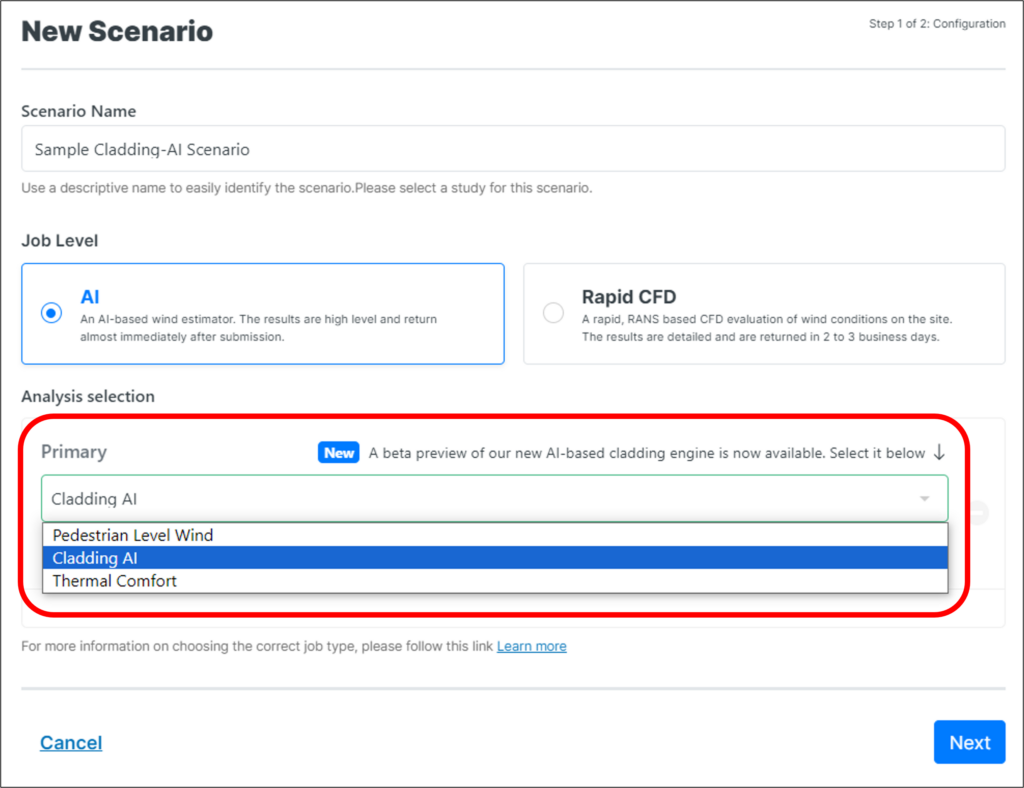
If you do not have access to Cladding-AI please reach out to your Orbital Stack Representative or contact Support@OrbitalStack.com
• Duplicate Scenario
To duplicate the geometry, metrics, and/or parameters of a previously run scenario, go to the Project Properties section, navigate to the Scenarios tab, and click Duplicate next to the scenario you wish to copy.
• Select Output Metrics
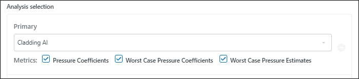
For additional information on these metrics, please visit Cladding Pressures Explained.
2.2 Upload and Categorize Geometry
Upload your geometry STLs into each specified bucket.
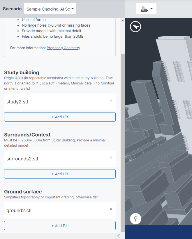
• Cladding AI Ground Geometry
Cladding AI assumes a flat ground geometry. For proper wind profile scaling, the intersection of the ground plane and study building should be at an elevation of z=0m. As with other simulations, please ensure building geometry fully penetrates the ground surfaces, as elevated or floating geometry will result in wind being simulated as passing underneath these buildings.
For additional info, please reference our Preparing Geometry Cheat Sheet.
• Review Geometry Integrity
Before finalizing your simulation parameters, we strongly recommend checking your files to confirm that they are formatted properly in accordance with the considerations which appear on the left of the screen. The viewer will ask you to check off each of these items before moving on to select simulation parameters, though this is not strictly necessary.
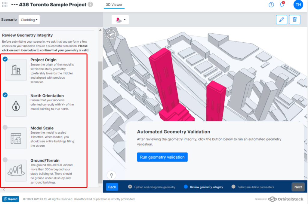
You are now prompted to “Run Geometry Validation”
The viewer will warn you of potential issues within your geometry, i.e. surfaces are volumetric when they should be a single flat surface. If this happens, you can click the button “Fix Geometry Files” which will take you back to the geometry upload page allowing you to remove your file and reupload a corrected file.
If no issues were found in your geometry files, you can proceed by clicking “Next” in the bottom right of the screen.
2.3 Select Simulation Parameters
• Pressure Coefficients
Input your Reference Height and select your Profile Correction from the drop-down list.
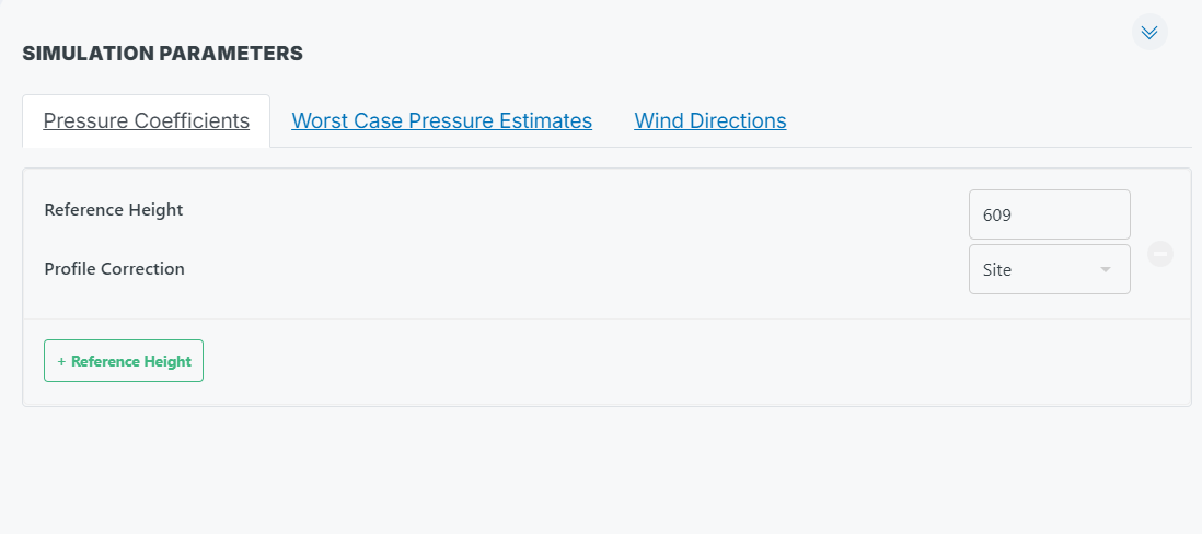
• Default Reference Height
Orbital Stack uses a default reference height of 609m. Therefore, by default, pressure coefficient results will be in reference to this height. During simulation setup, users can specify other reference heights and results will be scaled appropriately for each included height.
For simulations with multiple study buildings at different heights, we do not support setting reference heights per building – each result layer uses only one of the user defined reference heights. Setting one reference allows comparisons to be made between buildings and ensures all displayed results share a common reference height.
The AI was trained on scenarios with single study structures. As a result, we recommend analyzing only a single study at a time.
• Worst Case Pressure Estimates
Choose to enter either Internal Pressure (kPa) or Specify Building Roof Height.
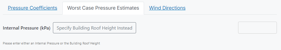
For additional information on internal pressures, please visit Cladding Pressures Explained.
• Return Period Calculations
You can specify up to four return periods and Orbital Stack will determine pressure estimates for each. For each return period, you are required to enter four parameters:
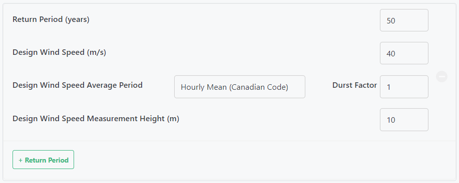
For additional information on each, check out our post on Cladding Pressures.
• Wind Directions & Terrain Considerations
Choose between eight (8) and sixteen (16) wind directions.
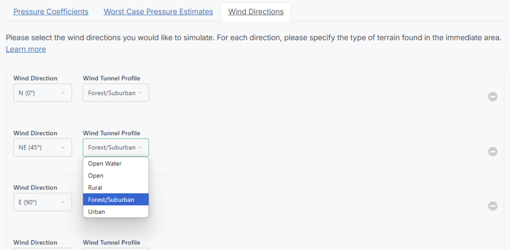
For additional information on the different terrain types, check out our post on Wind Directions and Terrain Considerations.
2.4 Submission
Once you are satisfied, click “Submit“.
A pop-up window will appear confirming the total cost of the simulation (in credits). Once you have read and checked the box to confirm that you have read the Terms and Agreement, click “Submit Scenario“.
After submitting a cladding simulation, the page will refresh and results will render within a few minutes*.
*Note: If there are issues with your submission (i.e. unprepared geometry and/or unaligned Simulation Parameters), results may take additional time.
Please do not hesitate to Contact Us with any questions!