
Video Tutorial – How to Prepare Your Geometry
1. Requirements on Input Geometry
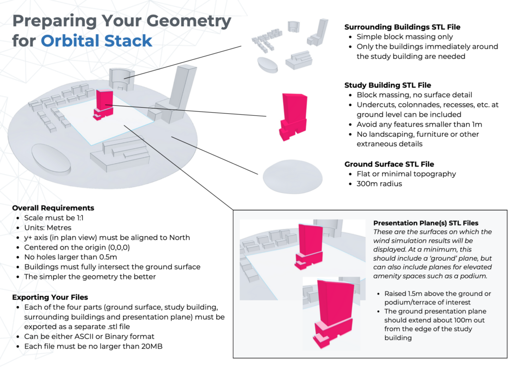
Orbital Stack accepts the input geometry in the form of .stl files. Please ensure that the geometry aligns with the following parameters;
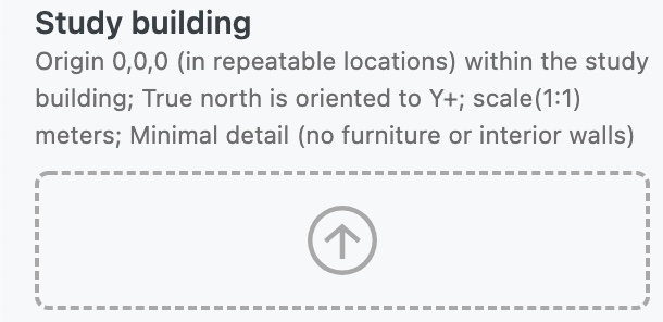
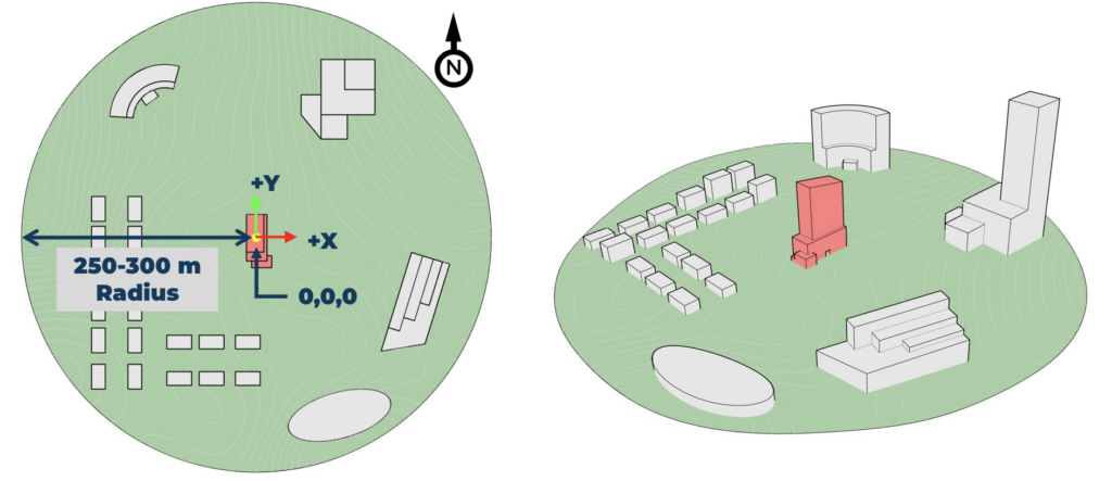
- True North is oriented to Y+ in plan view
- The files represent the geometry in full scale (1:1) Meters
- Each simulated configuration will have their own set of unique files
- Geometry should not contain larges holes or missing faces (anything wider than 0.5m)
- Context buildings should fully penetrate the ground surface
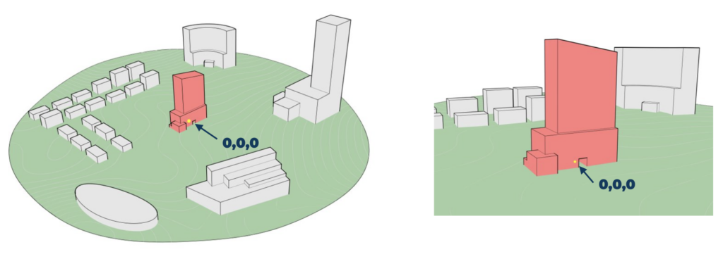
- Model geometry has an origin [0,0,0] at ground level near the center of your study building (the origin location should be reproducible by you so that future scenarios are aligned to the same origin)
2. Tools that Support STL
Orbital Stack can accept Binary or ASCII formatted .stls. There are many programs that support stl exporting.
The following are a few commonly used programs that support direct .stl exporting, however, feel free to use the software/exporter of your choice.
- Sketch Up
- Revit 2021
- 3DS MAX
- AutoCAD 3D
- Rhinoceros (Rhino can also be used to import from most programs above including .dwg and .skp)
Please export only part of the model, not the entire model (i.e. small objects such as furniture should not be included). Typical file size should be 20 megabytes or less. If you run into longer than 15 minutes of upload time, please check your file size and model details. For further assistance, please contact us directly at support@orbitalstack.com
3. Preparing the Input:
3.1 Files
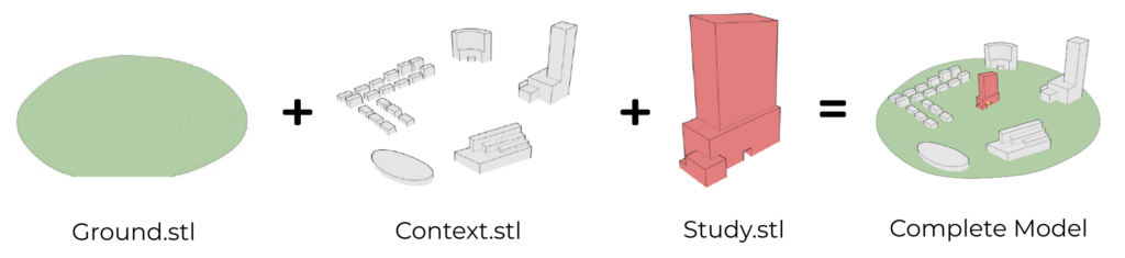
For each configuration, ensure that the base geometry is separated into three (3) distinct parts and each exported as an individual .stl file;
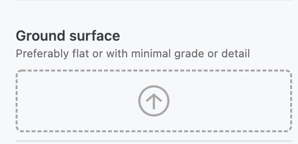
- Ground.stl – Minimal detail preferred, simplified topography or important grading, otherwise to be created as a flat plane, extending past the extents of the Context.stl. For additional guidance on modeling your ground surface see our post on Modeling Terrain.
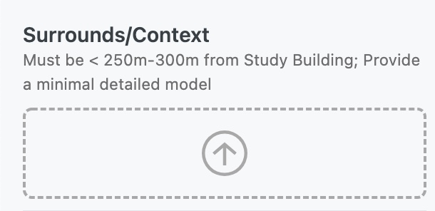
- Context.stl – Includes surrounding buildings between a 250-300m radius from the project site. If you require surrounds, see Automatic Generation of Surrounds
- Study.stl – Contains the elements that form the basis of the proposed development, or an existing onsite structure to be demolished (separate configuration)
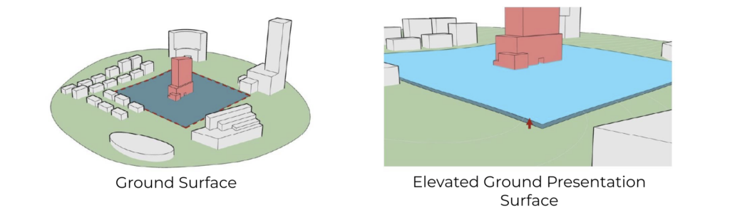
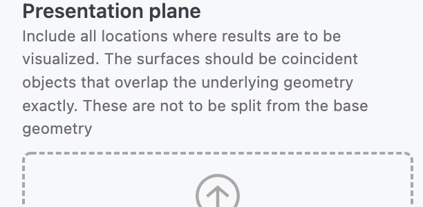
3.2 Presentation Surface(s)
A presentation plane / surface should be present at all locations where results are to be visualized;
- This would include locations such as:
- The ground surface around the project site
- Accessible outdoor amenity spaces, podiums, and rooftops
- Other important elevated surfaces with areas wider than 3m and larger than 15m2
- These surfaces must be raised by 1.5 meters above the locations for which results are desired
- Not raising the presentation surfaces will cause results to become distorted, or not show up at all
- All presentation surfaces are to be exported separately or according to the desired presentation groupings.
- E.g.
- Presentation_ground.stl (all ground level results)
- Presentation_amenity.stl (all above ground spaces)
- Presentation_balcony.stl (all balconies)
- E.g.
- It’s important to export the ground plane separate from above grade spaces

- Snip out a portion of the ground surface around the main study area
- Copy the new surface and raise vertically by 1.5 meters
- Add raised surface to a new layer and export as a .stl file (e.g. Presentation_ground.stl)
- Snip out above-ground surface(s) (e.g. terraces, rooftops, etc.)
- Copy the new surface(s) and raise vertically by 1.5 meters above the original surface(s) from which you copied them
- Add raised surface(s) to a new layer and export as a .stl file (e.g. Presentation_amenity.stl)
3.3 Overlay
The overlay bucket is for visualization of streets, sidewalks and objects that do not influence the simulation. Since your presentation surfaces are raised 1.5m it is important to raise the overlay layer by 1.7m above grade to ensure visibility above results.
Download our Geometry Preparation Cheat Sheet for quick reference.
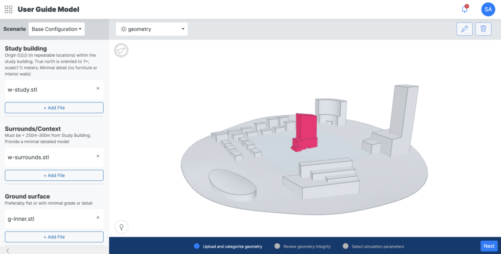
3.4 Upload to Orbital Stack
Export the .stl files and upload to the Orbital Stack Viewer
- A total of four (4) .stl files should be used for each configuration (Ground.stl, Context.stl, Study.stl, Presentation.stl)
For a more in-depth explanation, visit the Add New Scenario page.
To get started using Sample STLs click here
4. Orienting The Geometry
4.1 Model Origin
- Directions: Translate the desired geometry using a move function such that the center of the development/project/domain is located at the 0,0,0 position of the default coordinate system origin. Ground level should be at 0 in the Z value.
- Background: Model programs have user coordinate system reference origins and each one handles it slightly different. Some allow for that reference axis to be relocated and aligned, however, it may or may not respect that base point upon export. All programs have a “world” or default origin at 0,0,0 with +Y being up in a plan view. We internally translate our models using Rhinoceros close to the “world” 0,0,0 point which never changes. The relationship to this point is totally dependent upon how the initial model is created by the first person to start drawing (or has subsequently been moved there after).
- Models can also be geo-referenced to their lat/long position on the earth. Orbital Stack is not equipped to manage that translation. As described above, it will be necessary to export your geometry against a 0,0,0 origin within your study area.
- In many cases the client geometry will not be located at 0,0,0 and would simply need to be moved to be centered around the default 0,0,0 position
4.2 Model North
- Directions: Rotate the desired geometry around the 0,0,0 point of the default coordinate system origin using a rotate command such that True North aligns with the +Y axis in a top (plan) view.
- Background: As above, orientation is dependent on how they set up the model. Some programs are just noted with a rotated north arrow in titleblocks but geometrically are actually set to “Project North” vs. “True North” to align better with standard paper sizes. This has no geometric relevance to True North and is simply documentative.
- If the geometry is not aligned to true north which is industry standard assumed to be aligned with the +Y axis, this is accomplished with a rotate command.
5. What don’t we need?
Incorporating detail into working models has many advantages from conveying design intent, to space planning, to helping create immersive graphics that can feel incredibly realistic. As much as we at Orbital Stack love to envision ourselves in the project on a personal level, high levels of detail within the model is not required for the simulations. The following are some examples of common elements that can be omitted from the files being uploaded to Orbital Stack;
Small Site and Context Elements (Surrounding Structure(s)):
- Street level features such as temporary seating and tables, art sculptures, fountains, bicycle racks, small signage, fabric canopies or umbrellas, open railings, streetlights
- ground changes less than 1m
- People, animals, and vehicles
- Landscape plantings (trees can be added, for guidance on modeling trees, please check out Modeling Landscaping Features)
- Small sheds or outbuildings, temporary structures, shipping containers
- Porous elements such as radio antennas or rooftop mechanical equipment on surrounding buildings
Small Building Elements (Study Structure(s)):
- Due to the size of the domain, simulations are best suited to a simple block massing level of detail. Exterior cladding elements such as the following are not required:
- Parapets shorter than 0.5m
- Fins and façade details protruding less than 0.3m
- Sun shading elements
- Thin trellises and columns less than 0.5m in dimension
Interior Elements (Study Structure(s)):
- As these are externally simulated studies, interior elements are not required. In some cases, an indoor/outdoor space with large openings may be studied in which case things like the following need not be included;
- Plumbing elements such as toilets, sinks, piping
- Electrical elements such as lights, wiring, switches, audio/visual equipment
- Heating, cooling and ventilation elements such as ductwork, equipment, diffusers. Note than naturally ventilated spaces may require appropriate openings
- Other interior elements such as people, tables and seating, appliances, gym equipment, wall dividers, and temporary or movable elements
6. What to include?
Despite small details not needing to be included in geometry files being uploaded to Orbital Stack, some details help to create a more realistic environment in the simulation and can aid in providing a more comprehensive simulation. The following are some good examples of elements to include.
Site and Context Elements (Surrounding Structure(s)):
- Raised roadways & rail, overpasses and bridges, large berms (generally greater than 5m in height)
- Tunnels, and underpasses (generally greater than 5m below ground)
- Large billboards and signage (generally of 20m2 or more)
- High walls and solid fences near the project site (generally of 3m or more)
- Large canopies, amphitheaters, and transit shelters creating significant blockage
- Undercuts and large canopies on buildings adjacent to the site
- Massing changes in surrounding buildings greater than 3m (e.g. change in roof level or step back)
Building Elements (Study Structure(s)):
- Large canopies
- Undercuts or overhangs at ground and amenity spaces
- Columns larger than 0.5m in minimum dimension
- Parapets higher than 0.5m
- Mechanical screen walls and equipment (excluding small piping)
- Changes in vertical or horizontal massing greater than 0.5m
- Solid balustrades
7. Detailed Export Steps for Commonly Used Tools
- Revit 2021 and later
- Prepare the geometry and ensure only the desired objects are visible
- In a 3DView, select File -> Export -> CAD Formats -> STL
- Choose the following settings;
- Format: Binary
- Resolution: Fine
- Units: Meters
- Repeat for the object(s) that describe the intended .stl
- https://knowledge.autodesk.com/support/revit-products/learn-explore/caas/CloudHelp/cloudhelp/2021/ENU/Revit-DocumentPresent/files/GUID-93AE8701-3958-43E9-8D95-0C1650B88061-htm.html
- Rhinoceros
- Ensure the model units are set to Meters and object(s) are scaled appropriately
- Select the object(s) that describe the intended .stl, for ease, these may be organized onto separate layers
- With the final geometry selected, choose File -> Export Selected
- Choose the .stl file type and set to Binary through the options popup. Exporting open objects is to be checked
- If objects are NURBS geometry, a prompt will appear to set the desired mesh triangulation
- http://docs.mcneel.com/rhino/5/help/en-us/fileio/stereolithography_stl_import_export.htm
- Sketch Up
- Prepare the object(s) that describe the intended .stl (remove hidden/unwanted geometry from components and groups)
- Select the objects to be exported Use File -> Export -> 3D Model…
- Set the file type to .stl and choose the following options
- Format: Binary
- Units: Meters
- https://help.sketchup.com/en/sketchup/importing-and-exporting-stl-files-3d-printing#export-stl
8. Automatic Generation of Surrounds
A surrounds model is one of the four geometry files needed to run a simulation. This context model includes all the buildings that surround the building that you are studying.
We understand that as a designer you may not have access to the surrounding buildings and as such we have provided you the ability to automatically generate them using OpenStreetMap directly in our project creation workflow.
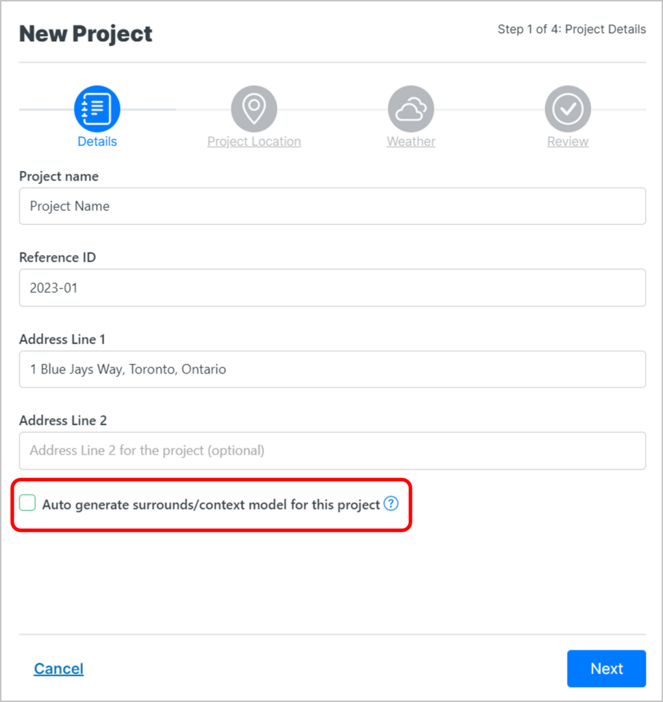
You can request these initially in the creation of your project tile by selecting the option to “auto generate surrounds/context model for this project”:
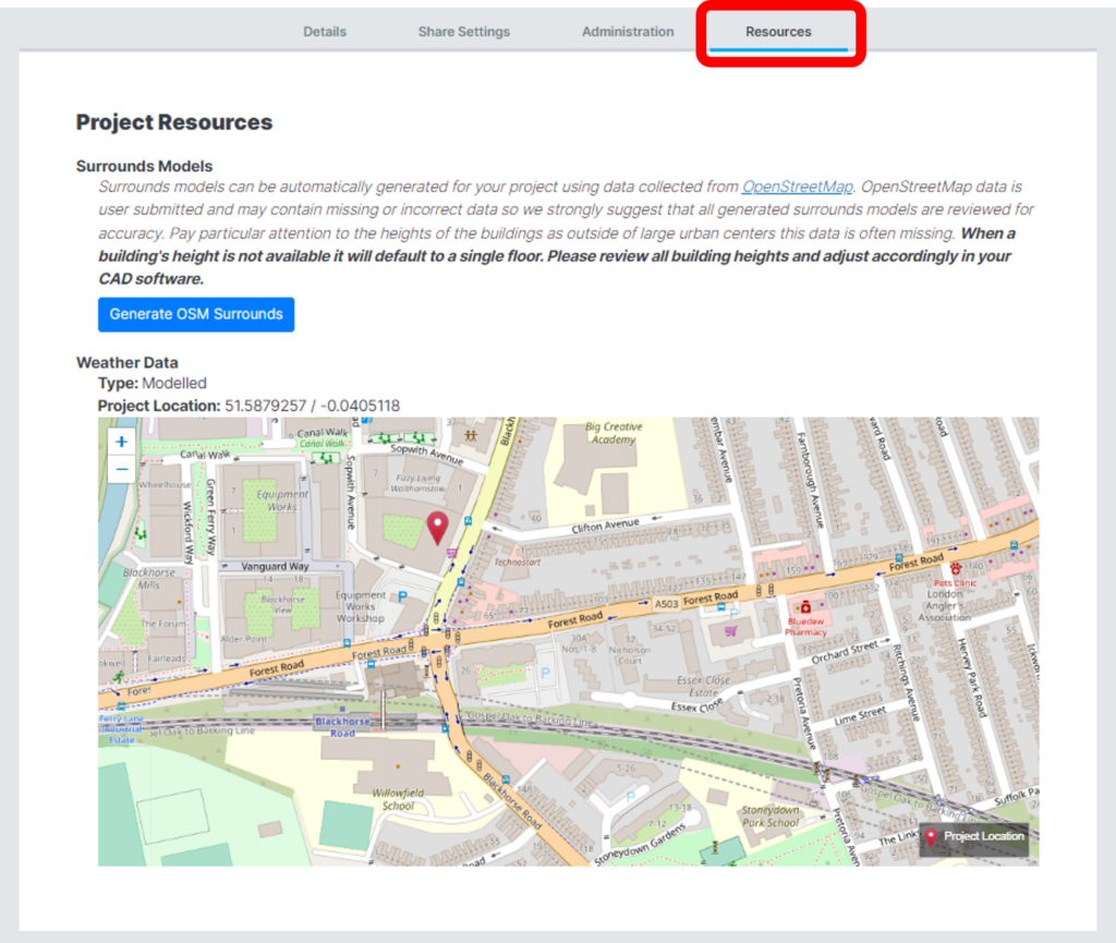
Once your project tile has been created, you can download this file from the Resource tab in the “Properties”.
Note: In generating this file, the Latitude and Longitude must be the center of your study model, if it is not, you can manually adjust after downloading. The surrounds generated will cover half a kilometer in each direction from the center of your study model.
Now click on the Resources tab, and click Generate OSM Surrounds. The surrounds STL file will download directly to your computer. Please thoroughly read the notes on this page as the STL file may contain missing or incorrect data. Buildings where the heights are unavailable will appear as a single floor building.
Now that you’ve created your surrounds file, please thoroughly review and make the required updates, including deleting buildings that are to be demolished and checking for accuracy of building heights. If you find building heights are either not available and/or incorrect, it is your responsibility to adjust accordingly in your CAD software prior to uploading the final STL into the Orbital Stack Viewer. The most important buildings are in the immediate vicinity of your site and any major buildings further out.
Once you have thoroughly reviewed the surrounds and you are satisfied with its content, you can now export as an STL file and then proceed with uploading it to the Orbital Stack viewer – see Add New Scenario instructions