Surface pressures (or cladding pressures) are crucial in the structural analysis of building designs as they quantify the effects of wind pressure on different surfaces of a structure. This data is often calculated as a set of pressure coefficients. Pressure coefficients are dimensionless numbers that represent the ratio of the pressure exerted by the wind on a surface relative to the dynamic pressure of the wind. By using pressure coefficients, engineers can apply different climate conditions to their analysis and predict how wind forces will impact various parts of a building.
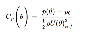
Pressure coefficients for a given wind direction, Θ, are defined as follows:

Where:
- p: normal (or perpendicular) pressure on the façade of the building at that location, for the given wind direction, Θ.
- p0: background atmospheric pressure
- rho: air density
- U_ref: Reference wind speed (which by default, for Orbital Stack, is an hourly mean windspeed at 609m in site-specific terrain roughness) for the given wind direction, Θ.
As mentioned above, a pressure coefficient is a non-dimensional way of communicating the pressure on a building’s facade. The advantage of using pressure coefficients is that even if your approach speed (reference speed) or air density at the site changes, the Cp value stay relatively constant.

When a design is analyzed using a wind tunnel study, a time series of pressures are recorded at each pressure tap location. A statistical analysis of this time series is then conducted to determine the minimum, maximum, and mean pressure along with the RMS variability for each measurement point on the building surface. These are recorded as pressure coefficients:
- Cp_min: The maximum suction pressure for the given wind direction (expressed as a pressure coefficient) expected to occur once during a typical hour
- Cp_max: The maximum positive pressure for the given wind direction (expressed as a pressure coefficient) expected to occur once during a typical hour
- Cp_mean: The mean pressure on the building surface for the given wind direction (expressed as a pressure coefficient)
- Cp_RMS: A measure of the variability in the pressure signal, expressed as the root mean squared of the pressure signal, non-dimensionalized like the other pressure coefficients.
Orbital Stack predicts these pressure coefficients directly for each wind direction in the simulation. First, the building geometry is converted into a mesh of triangular cells. The above set of four pressure coefficient values are then returned for each wind direction and each cell, providing a detailed pressure data across the surfaces of the study geometry.
Reference Frame
By default, Orbital Stack’s reference frame for pressure coefficients is 609m using the site specific wind profiles specified for each wind direction during simulation setup. Therefore, in order to dimensionalize the data, users must multiply the coefficients by a windspeed scaled to the correct wind profile and calibrated to 609m.
When setting up a simulation, the user has the option to define additional reference frames. A reference frame is defined by:
- Reference Height: This represents the height above ground that the reference windspeed (U_ref) is measured at for the Cp formula specified above. Typical choices for reference height would be the 609m default, 600m, or building height.
- Reference Profile: This represents the wind profile that was used for the reference windspeed (U_ref) when calculating the Cp (in the formula above). The options are to use the Site Profiles specified when setting up the simulation, or to convert everything to Open Profile.
- Site Profile: The Cp values for each wind direction will reference their unique profile. When dimensionalizing the data with a design wind speed, each wind direction must be scaled with a slightly different velocity (adjusted to the appropriate profile).
- Open Profile: All Cp values, for every wind direction, have been adjusted to reference an open profile. As such, all Cp values can be dimensionalized with a single design wind speed scaled to the Reference Height specified.
Each Reference Frame will generate a complete set of Directional Pressure Coefficients, Worst Case Pressure Coefficients, and Directional Pressure Coefficient Plots.
Available Results
Orbital Stack provides several ways to visualize, interpret, and combine the results of the directional pressure coefficient simulations.
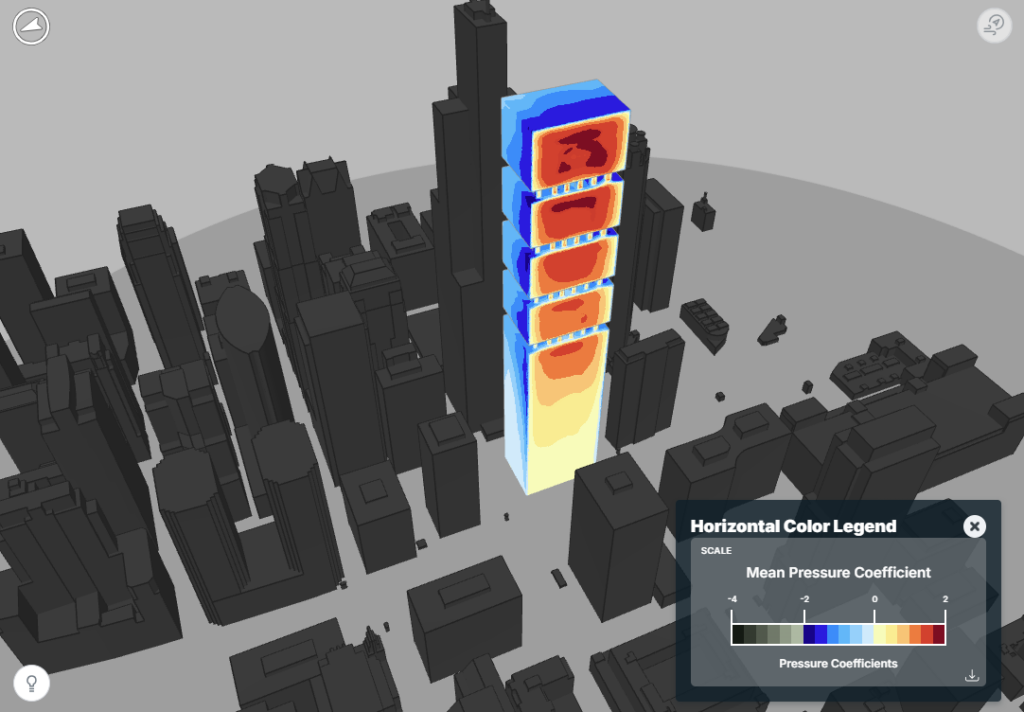
Directional Pressure Coefficients: These are contour plots on the surface of the building for each of the four pressure coefficient values (min, max, mean, RMS). Results are output for each wind direction specified. These results are referenced to the Reference Frame specified when setting up the simulation. The reference frame is included in the name of the layer.
Directional Pressure Coefficient Plots: These plots (available in the Data Panel) allow the user to inspect detailed pressure information for individual points on the building. For each selected point, the software will show all four pressure coefficient values for each of the wind directions on a single plot, with the wind angle along the horizontal axis.
Worst Case Pressure Coefficients: A worst case contour is generated for each of three metrics (Cp_min, Cp_max, and Cp_RMS) for each Reference Frame. In each case, the contour plot displays the Cp value of the worst wind direction (ie the most extreme Cp value) at each cell location. This plot provides an indication of the extreme Cp values to expect around the building.
Worst Case Pressure Estimates (Dimensionalizing the Data): Orbital Stack offers the user the ability to dimensionalize the simulation results using a design wind speed and a worst-case strategy. This means that the pressure coefficients are converted to actual pressures (in kPa) using the design windspeed, reference height, approach roughness, and an internal pressure estimate. For each cell location, the worst case pressure is then returned (highest positive value for Worst Case Maximums and lowest negative value for Worst Case Minimums).
Dimensionalizing the Pressure Coefficients
As described earlier, Orbital Stack will dimensionalize the pressure coefficients into worst case pressure estimates. These estimates take into account both the external and internal pressure. Internal pressures are subtracted from minimum pressures and added to positive pressures. The pressure estimates are calculated as follows:

P_ex (Θ) is the external pressure estimate for the wind angle, Θ.

- U_609_site is the design wind speed scaled to 609m in site specific terrain roughness (as specified for wind direction, Θ), expressed as an hourly mean speed in m/s
P_in is the internal pressure, calculated in one of two ways:
- read directly from user input as a single, fixed value in kPa above atmospheric pressure
- calculated using building roof height and enclosure classification as follows:

- GC_pi is the internal pressure coefficient derived from the enclosure classification
| Building Enclosure Classification | GC_pi |
| Open | 0 |
| Partially Enclosed | 0.55 |
| Enclosed | 0.18 |
- U_h-roof_site is the the design wind speed scaled to building roof height in site specific terrain roughness (as specified for wind direction, Θ), expressed as an hourly mean speed in m/s
Design Wind Speed
When dimensionalizing the pressure coefficients, Orbital Stack requires the following information from the user. The user can specify multiple design wind speeds and will receive one set of results for each choice.
Return Period: Specify the number of years associated with the return period for which the pressures are being calculated. Note that the value is only used as a label on the output results and is not used in the calculation.
Design Wind Speed: This represents the wind speed, in m/s, that is used to calculate the reference pressure. It is typically obtained from code tables and represents the expected peak wind speed for the project’s geographic location and return period. Please ensure this value is input in meters per second. These values can be obtained from code sources like the ASCE Hazard Tool in the US (https://ascehazardtool.org/)
Design Wind Speed Average Period: All Orbital Stack Cp data has been generated based on hourly mean wind data (rather than 3 second gust data). As such, Orbital Stack requires an hourly mean design wind speed. Should you want to input a wind speed of another average period, please choose the appropriate selection from the drop-down list (Hourly Mean, 10 Min. Average, or 3 Sec. Gust). The corresponding Durst Factor will automatically populate based on your selection.
There is also a Custom Durst Factor selection if you need to convert from another average period.
Design Wind Speed Reference Height: This is the height at which the design wind speed data has been determined or measured (in meters) – i.e. the height of the meteorological station above local ground. This height is usually 10m.
Design Wind Speed Scaling
Design Wind Speed Scaling
Orbital Stack produces cladding results based on hourly mean design windspeeds (Canadian Code) and accepts hourly means by default. To input design wind speeds of different periods, an appropriate Durst factor is used to scale the speed. Users can select an appropriate Durst factor to convert US Code (3s gusts) or EU Code (10min average) directly in the parameter setup page or specify a custom Durst factor to scale other design wind speeds.

Regardless of what Durst factor is used, please note that all design wind speeds and reference heights must be converted to SI units before input and conversion – meters per second (m/s) and meters (m) respectively.
Internal Pressure
As described above, internal pressure is used to calculate the net peak pressures on the façade of the building. Internal pressure is represented as a deviation from atmospheric pressure. Internal pressure can be calculated by Orbital Stack using the Building Roof Height and the Enclosure Classification, or by specifying a value explicitly. Toggle between modes by selecting either Internal Pressure (specified in kPa, usually < 1kPa) or Specify Building Roof Height (specified in meters).
Explicit Value of Internal Pressure: If providing an explicit value for Internal Pressure, it is generally calculated using the governing code for the project. In general, using ASCE will result in the same positive and negative internal pressure (+/- 0.24 kPa or 5 psf for example). At the moment, Orbital Stack only supports a single internal pressure. For codes that may result in distinct values for positive and negative internal pressures (-0.32 kPa, and +0.48 kPa), such as the EuroCode, it is recommended to use the larger of the two values in order to remain conservative.
Building Roof Height: Used when asking Orbital Stack to calculate the internal pressure.
Enclosure Classification: Used to determine how easily outside pressures balance through the building. This value is only used if Orbital Stack calculates the internal pressure. Specify the Enclosure Classification by selecting an option from the drop-down menu.
- Fully Open
- Partially Open
- Fully Enclosed