Getting Started Roadmap

Our Resources for your Cladding AI Simulations

Resources for your Cladding AI Simulations

Login here, then follow the next steps

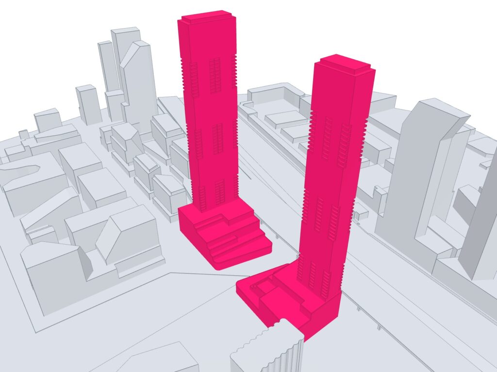
Don’t have your own geometry prepared? No worries, we have some sample projects you can download that are simulation-ready!

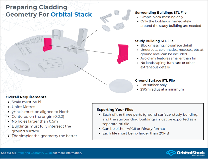
Our Cheat Sheet provides insights into best practices and potential pitfalls to avoid when preparing your geometry for the Orbital Stack Viewer.

While the video tutorial is available for use, please remember a presentation plane is not necessary for your cladding simulation.
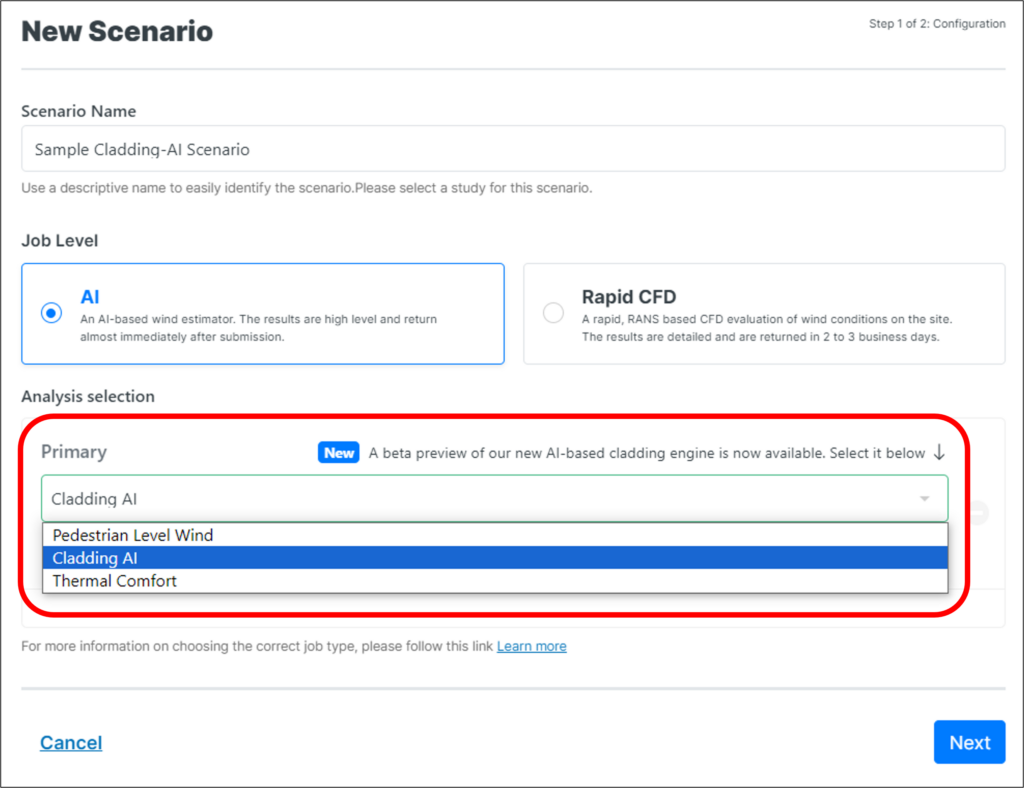
Scenario Creation

Select Cladding AI from the Analysis Type dropdown

Weather Station Selection

When it comes to conducting simulations within the Orbital Stack Application, choosing the right weather station is crucial. Please review our help site page Weather Station Selection for guidance.

Pressure Coefficients

An AI simulation is run for each of the wind directions specified when configuring the Scenario. Each simulation / wind direction returns a set of four pressure coefficient values: the mean, the minimum, the maximum, and the RMS (variability).

Pressure coefficients are defined as follows:
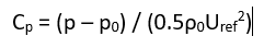
Where:

p: normal pressure on the façade of the building at that location

p0: background atmospheric pressure

rho: air density

Uref: Reference wind speed which for OS is defined at 600m.

The pressure coefficient is a non-dimensional way of communicating the pressure on a building’s facade. The advantage of using pressure coefficients is that even if your approach speed (reference speed) or density at the site changes, the Cp value stays the same.

Worst Case Pressure Coefficients

The worst-case pressure coefficient is determined by identifying the lowest minimum Cp or the highest maximum Cp among all simulated wind directions at each location on the building. As with the directional Pressure Coefficients, this is a non-dimensional value and has no units.

Worst Case Pressure Estimates

The Worst Case Pressure Estimates are the envelope of the estimated peak positive and negative surface pressures in kPa. Like the Worst Case Pressure Coefficients, this is the lowest minimum or highest maximum pressure coefficient
among all simulated wind directions at each location on the building, but factored by the gradient height wind pressure and adjusted by the Internal Pressure (specified or calculated through the Scenario setup parameters). Orbital Stack adds or subtracts the internal pressure value to generate the most extreme pressure.

The gradient height wind pressure used in Cladding AI is based on the mean wind speed at gradient height, 600m above ground. This wind speed is derived from the Design Wind Speed (hourly mean in m/s) and Design Wind Speed Reference Height (in m) specified in the input parameters. See the Simulation Parameters section of this guide for further details.

Upload your geometry STLs into each specified bucket.

Note, the overlay bucket is optional.

For additional info, please reference our Preparing Geometry Cheat Sheet.

Internal Pressure

Internal pressure is used to calculate the net peak pressures on the façade of the building. It is represented as a
deviation from atmospheric pressure. Internal pressure can be calculated by Orbital Stack using the Building Roof Height and the Enclosure Classification, or by specifying a value explicitly. Toggle between modes by selecting either Internal Pressure (specified in kPa, usually < 1kPa) or Specify Building Roof Height (specified in meters).

If providing an explicit value for Internal Pressure, it is generally calculated using the governing code for the project. In general, using ASCE will result in the same positive and negative internal pressure (+/- 0.24 kPa or 5 psf for example). At the moment, Orbital Stack only supports a single internal pressure. For codes that may result in distinct values for positive and negative internal pressures (-0.32 kPa, and +0.48 kPa), such as the EuroCode, it is recommended to use the larger of the two values in order to remain conservative.

Enclosure Classification

Enclosure Classification is used to determine how easily outside pressures balance through the building. This value is only used if Orbital Stack calculates the internal pressure. Specify the Enclosure Classification by selecting an option from the drop-down menu.

Project North Angle (°)

Projects submitted typically have true North align with the positive Y direction. For cladding studies, users may want to specify a ‘project North’ to align wind directions perpendicular to  building faces. If this is the case, input the desired Project North Angle relative to the positive Y direction (true north) in degrees and all wind angles will be referenced to project north rather than true north.

Return Period Calculations

You can specify up to four return periods and Orbital Stack will determine pressure estimates for each. For each return period, you are required to enter four parameters:

  • Return Period: Specify the number of years associated with the return period calculation. This is for reference purposes only.
  • Design Wind Speed: This is obtained from code tables and represents the expected peak wind speed for the location and return period. Please ensure this value is input in meters per second.
  • Design Wind Speed Average Period: By default, Orbital Stack will assume an hourly mean design wind speed. Should you want to input a wind speed of another average period, please choose the appropriate selection between Hourly Mean, 10 Min. Average, or 3 Sec. Gust. The corresponding Durst Factor will automatically populate based on your selection.
    • There is also a Custom Durst Factor selection if you need to convert from another type of average period.
  • Design Wind Speed Reference Height: This is the height at which the design wind speed data has been determined or measured (in meters). This height is usually 10m.
Wind Directions

Choose between eight (8) and sixteen (16) wind directions.

Terrain Types

Selecting terrain types for each direction provides a more fine-tuned analysis representative of the wider site area, beyond the surrounding buildings included in the model. Choosing the appropriate terrain is important because of how wind is influenced by that environment. For each selected wind direction, review the terrain from 300 to 2000 meters upwind of the site and choose the appropriate Terrain Type. For this, we recommend referring to satellite imagery (e.g. via Google Maps). Choose the Terrain Type that is predominant for that wind direction. For example, a mix of suburban but mostly open terrain could be classified as open to yield slightly windier conditions.

  • Open Water: Open water.
  • Open: Unobstructed and flat areas, ideal for large bodies of water, fields or parking.
  • Rural: Slightly obstructed areas, ideal for farmland or scattered low-rise buildings.
  • Forest / Suburban: Partially obstructed areas, ideal for wooded areas, parks, and suburban single family (one to two story) residential.
  • Urban: Highly obstructed area, ideal for high density cities two to five story buildings with the occasional high rise.

For additional information on each, check out our post on Wind Directions and Terrain Considerations.

Do you need help understanding your results, drop us a line and we can set up a call.


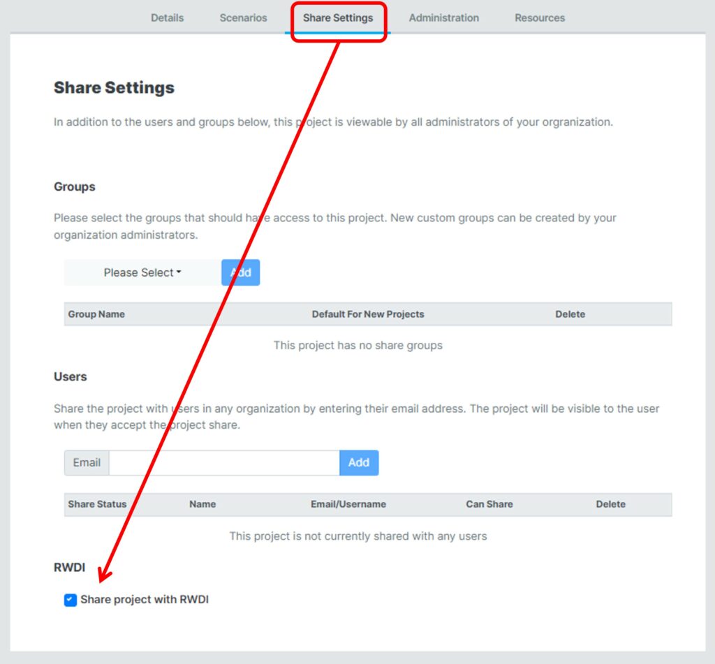
If you are booked for a call with an RWDI engineer, please share your project with RWDI under the share settings within your project properties.

Helpsite
OS Youtube
Book a demo